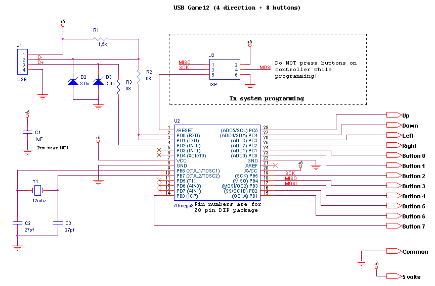
Gameport To Usb Wiring Diagram

Vt Commodore Ignition Wiring Diagram, Complete Wiring Diagrams For Holden Commodore VT, VX, VY, VZ, VE, VF, 5.36 MB, 03:54, 32,796, John Amahle, 2018-08-01T19:37:41.000000Z, 19, Vt Commodore Ignition Wiring Diagram, to-ja-to-ty-to-my-to-nasz-swiat.blogspot.com, 1272 x 1800, jpeg, bcm pcm 12j swiat nasz, 20, vt-commodore-ignition-wiring-diagram, Anime Arts
The gameport y cable works when used in conjunction with the gameport to usb adapter. The adapter will pick up the cable as one controller and supports four axis, four buttons and four additional buttons of a hat switch. The game has to be able to assign the buttons and axis of each controller. Its great to hear that dude. for ur question yeah you could geta a bunch of 10k resistors add them to a old gameport port and make a game port shield for the arduino and use it that way. and for the additional pot u need as a speed control just attach it to one of the analog inputs.
While the buttons for each joystick are simple buttons, the. The joystick port is an analog connection. It takes and ic to convert the analog to digital. Now you could hack apart another (mabye broken) usb game controller and use the chip to wire up your game pad, but this would be over doing it. Zapwizard, 14 nov 2002. The circuit connection is pretty much standard. The above diagram shows the wiring diagram as. So to be on the safe side, the wiring diagram in figure 4 is probably the safest way to go. If you have already bought a cable and it doesn't seem to work.
Gameport To Usb Wiring Diagram | USB Wiring Diagram

Gameport To Usb Wiring Diagram | USB Wiring Diagram

Free download program Game Port To Usb Circuit - letitbityellow
Gameport To Usb Wiring Diagram | USB Wiring Diagram

Joystick Logitech Wingman przejściówka Game Port na USB
GitHub - psaikko/teensy-dual-joysticks: Connecting two gameport controllers via USB using Arduino

Circuit for USB game controller with 12 inputs (8 buttons + 4 directions)

Gameport To Usb Wiring Diagram | USB Wiring Diagram
